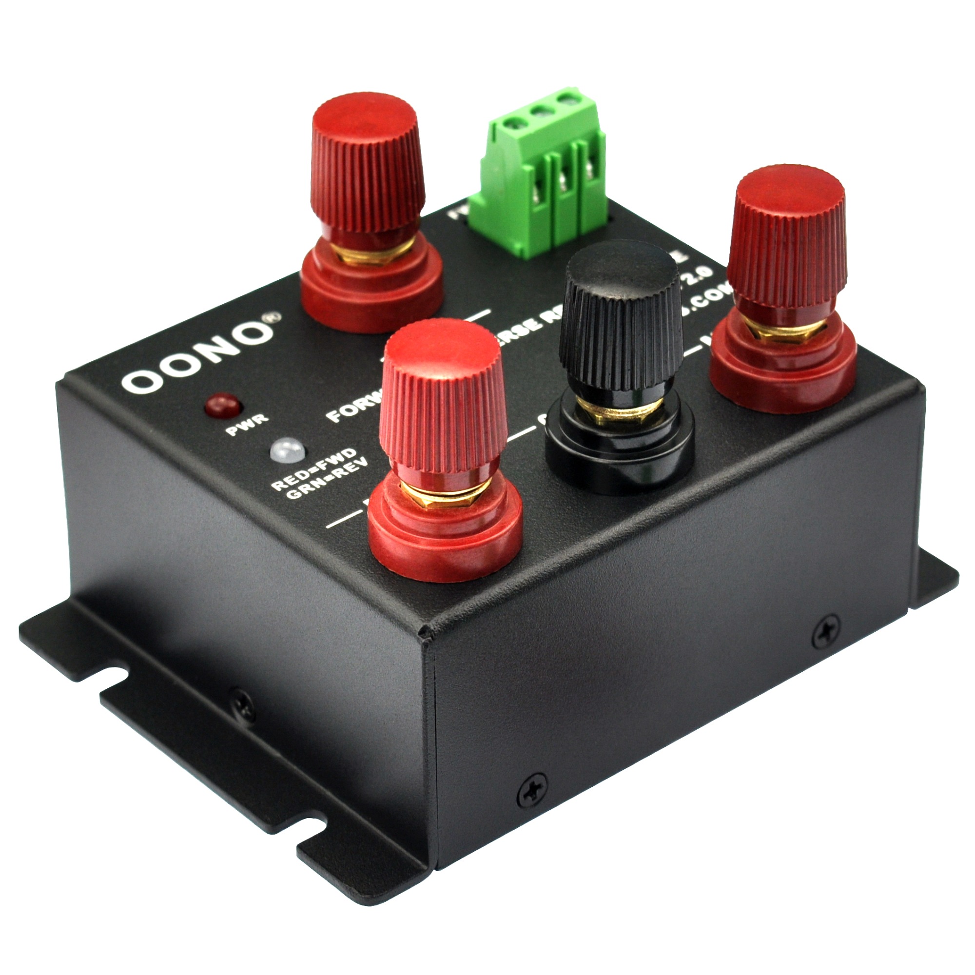

The IRF510 can handle roughly 5A (Id) up to 100 volts (Vds) in steady mode, but if using pulses (PWM) the current can go up to about 20A (Idm) if the pulses are small enough (high enough frequency) still, derate the current by about half for safety. The current and voltage handling will depend on the MOSFET (Q2 for speed control) and relay you use the MOSFET for relay switching (Q1) isn't important for this, it just needs to be able to handle the current and voltage needs of the relay coil. When working with more power try attaching a heat sink to the MOSFETs.If you decide to go over 15 volts connect the Vin and GND directly to the source and connect the Ground to the Micro-controllers GND.Make sure that you do not exceed 30 volts at Vin.Using two more colored wires connect the speed and reverse to two digital pins of your choice.Using two colored wires connect the Vin to your micro-controllers Vin pin And the GND to the GND pin.

Insert the motor controller into a breadboard.Plug or connect your motor to the motor pins on your motor controller.Either way make sure you look at the schematics diagram above. If you have placed your pieces differently or soldered the circuit together differently than just look at the schematics layout above. If you have designed and built it like I have than this should be easier and you can just follow the layout above. Now it is time to use your new motor controller.


 0 kommentar(er)
